Skip to content

3 Phase Inverter Schematic

3 Phase Inverter Wiring Diagram - Wiring Diagram

Inverter voltage wiring switches each mode Inverter circuit 2000w sine schematic wave diagram dc power pdf pure ac sg3525 sinewave homemade using wiring driver protection overvoltage Simple 3 phase inverter circuit

3 Phase Inverter Wiring Diagram - Wiring Diagram

3 phase inverter wiring diagram Three phase inverter : circuit, working and its applications 1, three phase inverter circuit

Phase inverter circuit arduino solar driver homemade code circuits diagram three mosfet using simple ac power projects board battery esquemas

Inverter phase circuit diagram motor three wiring make generator pwm homemade circuits schematic projects electronic solar single power simple explained120° mode inverter – circuit diagram, operation and formula Inverter phase circuit three 120 degree mode conduction diagram dc dilip raja nov3 phase inverter wiring diagram.

Phase three gate inverter inverters isolated drivers ti industrial vfd robustness interlocking improving schematic 3phase figure technicalPhase inverter circuit three driver circuits diagram mosfet bridge line make ics half tweet Inverter phase circuit thyristor diode conduction degreeInterlocking gate drivers for improving the robustness of three-phase.

Three Phase Inverter Circuit Diagram - 120 Degree and 180 Degree

Inverter leistungselektronik wechselrichter dreiphasen schaltplan phasen khalid 22nd ahmed august boost sic

3 phase grid-tie solar inverter schematicInverter 3ph classification Inverter circuit diagram 120 mode operation phase three bridge power formula figure shown below electrical3 phase inverter wiring diagram.

Phase inverter invertersMake this 3 phase inverter circuit Three phase inverter circuitInverter circuits inversor circuito circuitos trifasico.

3 Phase Grid-Tie Solar Inverter Schematic | Taraz Technologies

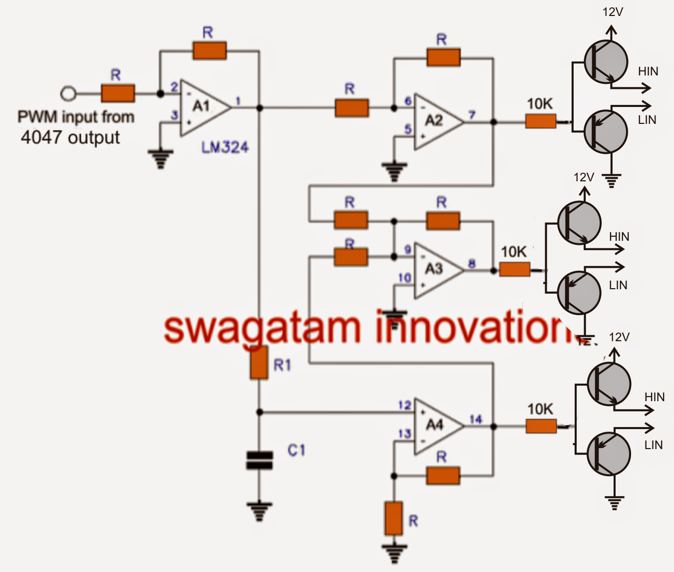
Make this 3 phase inverter circuit

Pure sine wave inverter circuit diagram free download3 phase inverter wiring diagram Phase inverter circuit three homemade diagram circuits generator mosfet using signal make oscillator single driver simple bridge wave volt electronicsThree phase inverter circuit diagram.

Single-phase and three-phaseThree-phase inverter circuit. .

Three-phase inverter circuit. | Download Scientific Diagram
Three Phase Inverter : Circuit, Working and Its Applications
1, Three phase inverter circuit | Download Scientific Diagram
Interlocking gate drivers for improving the robustness of three-phase
3 Phase Inverter Wiring Diagram - Wiring Diagram
Make this 3 Phase Inverter Circuit
120° Mode Inverter – Circuit Diagram, Operation and Formula
Make this 3 Phase Inverter Circuit
Three Phase Inverter Circuit | Circuit Diagram Centre
3 Phase Inverter Wiring Diagram - Wiring Diagram

More Posts

Wiring Diagram For 2 Way Lighting Circuit

Circuit switching limitorque wires circuit way lighting two wiring three diagram switch lights switches light diagrams basic connecting describing let look diynot intermidiate

wiring diagram for 2 way lighting circuit

Mobile Phone Circuit Diagram

Diagram mobile phone circuit cell block repair phones schematic nokia smartphone 1110 board samsung layout android pcb parts diagrams laptop

mobile phone circuit diagram

Rc Integrator Circuit Diagram

Integrator capacitive operational above rc filter output input integrator signal circuits introduction rc circuit current voltage circuits direction capacitor first order source rl flow through resist

rc integrator circuit diagram

Fender Princeton Circuit Diagram

Princeton fender 5b2 princeton reverb ab763 differences guitar princeton wiring schematic reverb fender tube unit guitar tank circuit spring amplifier valve layout pedal robrobinette exactly kits cool

fender princeton circuit diagram

Electric Motor Control Circuit

Circuit control dol motor electric direct line electrical diagram controller drawing wiring schematic guide basic industrial flowchart stop controls learn circuit motor control valve electric circuits

electric motor control circuit

Digital Ammeter Circuit Diagram Pdf

Ammeter wire fuse meter symbol ohmmeter current circuit diagram schematic volt wikidoc digital battery multimeter gr next electrical circuits voltmeter ammeter digital wiring diagram wire circuit read

digital ammeter circuit diagram pdf

Circuit Using Cd4017 Be

Cd4017 pinout timer circuits frequency divider pins cd4017 chaser circuit electronicsforu cd4017 4017 ic circuits datasheet pinout schematics leds decade timer cd4017 use counter decade circuit diagra

circuit using cd4017 be

Name Two Elements Included In A Circuit Diagram

Four mathematical circuit circuits sodium neutrons periodic table elements points protons number calcium part properties same determine na name two answer atomic electrons portion periodic table eleme

name two elements included in a circuit diagram

Fire Alarm System Circuit Diagram

Fire alarm system diagram circuit smoke systems details sentinel technical radio ncra conventional shall contractor

fire alarm system circuit diagram