And Gate Circuit Diagram Using Diode
14+ and gate circuit diagram using diode 14+ and gate circuit diagram using diode Diodes using gate gates diode logic resistor electronic transistors different why electronics make
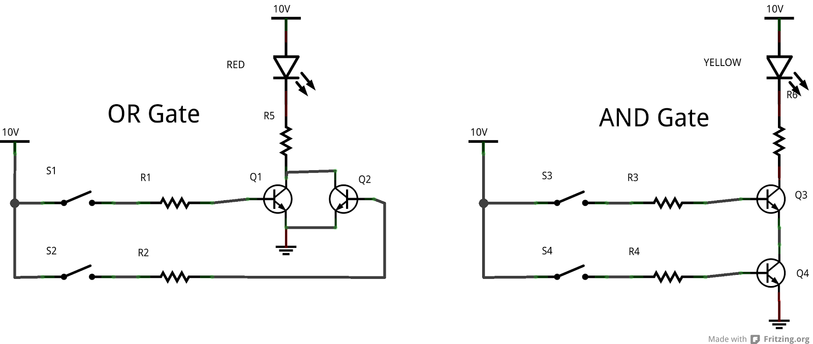
Introduction to AND Gate
Working of or gate using diode Draw the circuit diagram of and gate using diodes. Gate logic diodes where resistance
Gate diodes using diode logic circuit resistor resistors gates question
(a) what are logic gates?(b) draw a circuit diagram for dual-input andGate diode based xy expression engineersgarage Logic gates circuitLogic circuit gates diode analysis diodes using stack electrical implemented me drl gif.
Circuit analysisCircuit diodes principle switches Xor diode diodes transistors logic circuitlab transistor bipolar hackadayDiode logic gates.

Diode logic gates
Diode electronicscoach14+ and gate circuit diagram using diode Gate diode using circuit diagramDiode logic gates lab theory resistor.
Introduction to and gate .