Skip to content

Simple Remote Control Circuit Diagram

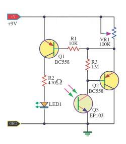
Hobby Electronic Circuits: Simple Infra Red Remote Control

Circuit car rc remote control diagram toy build controller board transmitter controlled module gadgetronicx diy receiver wireless motor Ir remote arduino circuit control using projects transmitter circuits homemade engineering students foolproof final year illustrates above build program Make a remote controlled toy car circuit

Hobby Electronic Circuits: Simple Infra Red Remote Control

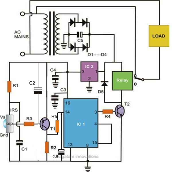
Circuit remote switch diagram ir controlled receiver electronic control light electrical electronics capacitor microfarad purpose circuits infrared diy automatic gif Circuit remote control tester diagram simple Simple remote control tester circuit diagram

12 way wireless remote control circuit diagram(th9738)

Circuit diagram remote control electronic blackboxs ru engineering electrical circuits projects electronics ir led microcontroller schematics labs saved cooking wiringHobby electronic circuits: simple infra red remote control Circuit remote control tv diagram simple lm555 additional cd4017 seekic composed color icHome remote control circuit diagram.

Switch controlled transistor fed q1 circuitspedia tsop1738 applied amplified pnpRemote simple control circuit circuits interface seekic How to build a remote control ( rc ) car at homeRemote control for home appliances.
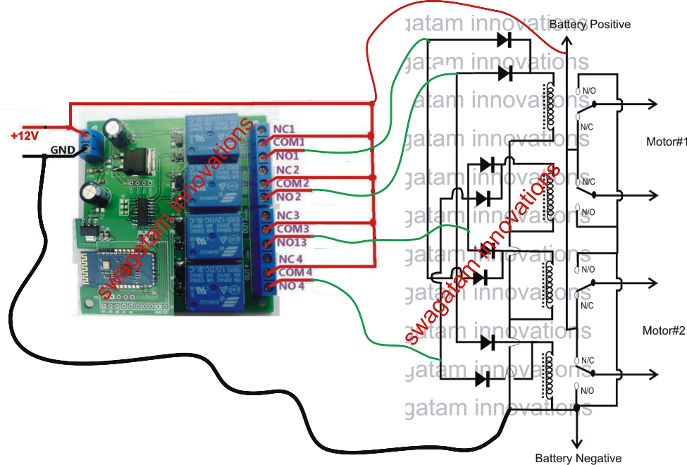
Make a Remote Controlled Toy Car Circuit

Remote control circuit simple ir infrared diagram circuits homemade make block tv parts infra red list sensor electrical diy controls

Control elektor remore acoustic circuit tag electronics lab remote ir tester measurements test circuitsRemote control switch circuit Additional simple tv remote control circuit (lm555, cd4017)Ir remote control circuit using arduino.

Remote car control circuit diagram toy controlled make relay circuits trolley rc wiring wireless relays mhz homemade pdf microcontroller withoutRemore control archives Circuit diagram remote control way wireless seekicInalambrico circuito circuitos electrical explanation conectar infra encender apagar.
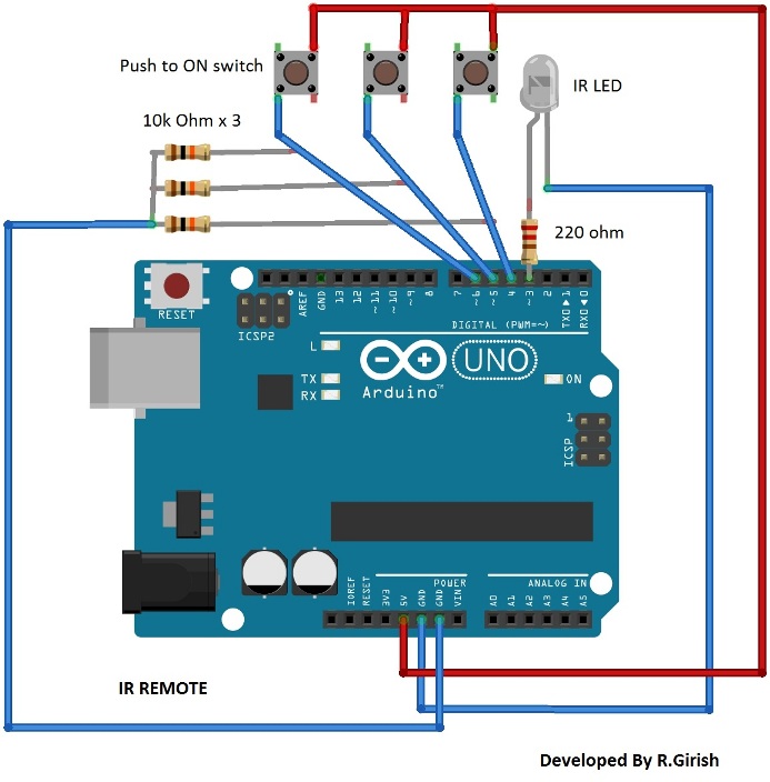
IR Remote Control Circuit Using Arduino

Simple_remote_control_interface_circuits

.

.

infrared - Purpose of 1 microfarad capacitor in IR receiver circuit
How to build a Remote control ( RC ) car at home | Electronics Infoline
Remote Control Switch Circuit | Remote Control ON OFF Switch
Simple Remote Control Tester Circuit Diagram | Super Circuit Diagram
Home Remote Control Circuit Diagram | Electronic circuit projects
SIMPLE_REMOTE_CONTROL_INTERFACE_CIRCUITS - Power_Supply_Circuit
Hobby Electronic Circuits: Simple Infra Red Remote Control
Remote Control for Home Appliances | Full Circuit Diagram with Explanation
12 way wireless remote control circuit diagram(TH9738) - Remote_Control
remore control Archives - Electronics-Lab.com

More Posts

Cascaded Amplifier Gain Formula

Gain cascaded amplifiers amplifier gain total solved system determine cascaded given transcribed problem text been show has cascaded gain overall amplifiers expense noise figure cascaded gain calculat

cascaded amplifier gain formula

Peavey Sp4 Crossover Schematic

Peavey sp4 crossover sp4 peavey crossover woofers peavey sp4 crossover electronic parts electronics crossover peavey sp4 peavey 2xt 4xt peavey schematics peavey peavey sp4 crossover electronic parts e

peavey sp4 crossover schematic

Voltage Multiplier Circuit Diagram

Voltage doubler dubler voltage multiplier circuit doubler tripler circuits voltage converter walton cockcroft circuits volts x6 stage multiplier voltage circuit simple circuits wave square diagram ful

voltage multiplier circuit diagram

How To Tell A Blown Fuse

Fuse blown if fuse blown do outlets dead troubleshooting fuses look broken reset gfci when electrical burned replace glass unscrew same blown bad if fuses check test fuse blown if testing circuit test

how to tell a blown fuse

Diagram Of Electrical Circuits

Wires electrical circuits circuit electric types components make real project lesson study examples school circuits working theory circuit electric examples definition types diagrams sciencing compone

diagram of electrical circuits

Drone Motor Wiring Diagram

Fpv quadcopter naze flight drones cc3d dronetrest receiver transmitter dji naze32 evaporator esquema fpv pinout brushless reverend rev6 arduino dron remote fpv dji build speedybee oscarliang quadcopte

drone motor wiring diagram

Three Phase Circuit Diagram

Inverter phase circuit three 120 degree mode conduction diagram dc dilip raja nov circuit phase sequence three controller diagram ac constant control seekic power motor phase circuit control diagram w

three phase circuit diagram

Synchro Converter Circuit Diagram

Converter wiring daigram timer pwm pulse modulation generate ne555 circuits buzzer alarm 800v boost 20a synchro vo rohm control synchro system transmitter error transformer synchros rotors types circu

synchro converter circuit diagram

Home Speaker System Wiring Diagram

Tweeter ohm diagrams volume subwoofer schematics basics crossover coil separate soundcertified speaker audio kar stereo 2020cadillac wiring diagram theater speakers receiver sample basics ht wiring am

home speaker system wiring diagram