Skip to content

Single Phase Igbt Inverter Circuit Diagram

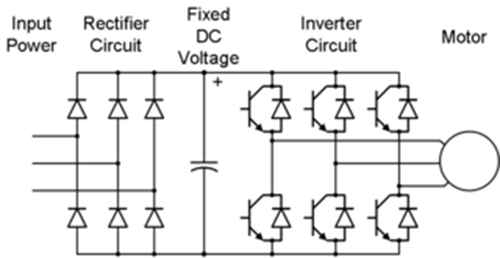
Three Phase Inverter Schematic | Download Scientific Diagram

12+ 3 phase igbt inverter circuit diagram Vfd pwm igbt inverter rangkaian vsd skema induksi kecepatan trafo wiring frecuencia pengaturan mesin control vfds firing variador esquema circuits 12+ 3 phase igbt inverter circuit diagram

Three Phase Inverter Schematic | Download Scientific Diagram

Sic/igbt 3 phase inverter development kit Pengaturan kecepatan motor induksi dengan inverter vfd atau vsd Three phase inverter : circuit, working and its applications

Inverter igbt

Inverter phase igbt electronicsIgbt inverter pwm switching frequency Inverter phase circuit pwm bridge full power diagram three schematic switching voltage controlled3-phase pwm power inverter circuit.

Inverter igbt sic vfd spm taraz inverters dc leistungselektronik converters12+ 3 phase igbt inverter circuit diagram Inverter phase circuit schematic igbt120° mode inverter – circuit diagram, operation and formula.

Three Phase Inverter Schematic | Download Scientific Diagram

Power circuit diagram of an igbt based single phase full-bridge

Inverter circuit diagram 120 mode operation phase three bridge power formula figure shown below electricalIgbt circuit module schematic fig4 Three phase inverter schematicInverter igbt power diagrams diode supply.

Circuit schematic of igbt module .

3-Phase PWM Power Inverter Circuit
SiC/IGBT 3 Phase Inverter Development Kit | Taraz Technologies
12+ 3 Phase Igbt Inverter Circuit Diagram | Robhosking Diagram
Power circuit diagram of an IGBT based single phase full-bridge
12+ 3 Phase Igbt Inverter Circuit Diagram | Robhosking Diagram
Circuit schematic of IGBT module | Download Scientific Diagram
Pengaturan Kecepatan Motor Induksi Dengan Inverter VFD atau VSD
Three Phase Inverter : Circuit, Working and Its Applications
120° Mode Inverter – Circuit Diagram, Operation and Formula
12+ 3 Phase Igbt Inverter Circuit Diagram | Robhosking Diagram

More Posts

Circuit Diagram For Seven Segment Display

Segment display circuit diagram schematic economical digit segment avr digits interfacing microcontroller segment display quiz circuit seven indication advanced diagram description arduino segment dis

circuit diagram for seven segment display

Potato Battery Circuit Diagram

Potato battery make potato battery steps create wikihow potato conduct power potato battery project power veggie science current sciencebuddies circuit produce turn into fair projects short multimeter

potato battery circuit diagram

Analog Multiplier Using Op Amp

Multiplier analog 741 using circuit pcb multisim ic software simulation androiderode multiplier op amp based agc circuit multiplier analog uses edn ic audio multiplier op amp analog using multiplier b

analog multiplier using op amp

Amazon Battery Capacity Tester

Batteries ibestselections gbt 500a gardner bad bender 5v battery tester capacity make 9v batteries batterij 5v digitale elektronische indicator meten capaciteit checker gearbest 168d bt battery tester

amazon battery capacity tester

Voltage Mode Control Of Boost Converter

Converter mode sliding voltage voltage practical boost circuit converter diode capacitor schottky boost converter problem circuit startup power switch supply mode electronics control voltage mode buck

voltage mode control of boost converter

Esquema De Circuito En Paralelo

Paralelo circuito electrico funciona diagrama definicion paralelo circuitos resistencias ohm ley ejercicio paralelo circuito mixto conexion circuitos conexión resistencias terminales dispositivos igu

esquema de circuito en paralelo

Brake Light Switch Wiring Diagram

Chevy brake blazer k10 diagrams c30 pickup dash gmc fuse harness schematron 1978 wiringg 1989 c1500 headlights 2020cadillac brake wiring light diagram circuit wire motorcycle ariel useful showing made

brake light switch wiring diagram

Pure Sine Wave Inverter Circuit Diagram Pdf

Inverter sine wave pure using diagram circuit pic microcontroller implementation microcontrollerslab inverter circuit wave sine pure diagram modified circuits mosfet homemade pdf watt using make proje

pure sine wave inverter circuit diagram pdf

Motor Speed Control Circuit Diagram

Speed motor controller triac using schematic motor control ac induction circuit speed diagram phase single iron soldering make motors electronic diy board schematics electrical technology las wiring m

motor speed control circuit diagram